| John Broskie's Guide to Tube Circuit Analysis & Design |
September 25 2024 Post Number 608
Super-Triode Designs I pointed that tubes have never been as expensive as they are now and that many NOS tube reserves have been depleted, so I advised against any design that used a dozen tubes, which had been his plan. I explained that while he might be able to find a dozen of those tubes today, it wasn't likely that he could do so again five years from now. I mentioned the super-triode arrangement as viable alternative, as it could yield the same sonic performance, while only using four tubes. Asked to explain the super-triode arrangement, I listed the three essential conditions to bring about super-triode functioning, which post 375 provided:
The second essential condition, "Using beefier devices, either tube or solid-state, to drive entirely—with no help from the triode—the external load impedance," is what troubled my friend—thus, his profound disappointment. As he saw it, if the triode didn't help drive the headphone, then the amplifier was simply a hybrid design, wherein the tubes pass on tube-sweetened signal to clunky solid-state output devices. In other words, if the triode is running a constant-current flow, it isn't delivering any output current into the loudspeaker, which means that it isn't driving anything. He saw this as effectively a morganatic marriage, aka a left-handed marriage, the wedding of the noble NOS tube to a commoner solid-state device, which could not inherit any of the noble tube's finer attributes. What if it could? Often when you encounter a conceptual roadblock, the best workaround is to find a good analogy. I began by stressing the need to obey the third condition, "Letting the triode control the output." I then delivered my analogy: A high-tech company's CEO, for example the late Steve Jobs, doesn't solder a single IC onto a PCB or lay out the PCB or devise the circuit on the PCB, yet he controls the company's output, i.e. its product. Without Steve jobs, Apple wouldn't be Apple. (And some would argue that Apple is no longer Apple.) To switch analogies, the ship's helmsman doesn't power the ship; he steers it. In much the same way, if the triode steers (controls) its beefy solid-state partner's output current flow, the triode imparts its electrical characteristics upon the solid-state device, which are both cheap and plentiful. In addition, MOSFETs and bipolar transistors can release huge torrents of current, by comparison triodes, even the 6AS7 and 6C33, are current-constrained. For example, the huge 6C33 power triode can deliver peak output current swings of 1A, which is impressive for a tube.
In contrast, the MJE15032, a TO-220 NPN 250V power transistor, can deliver 16A of peak current. Moreover, MJE15032 transistors can be bought for less than $2.
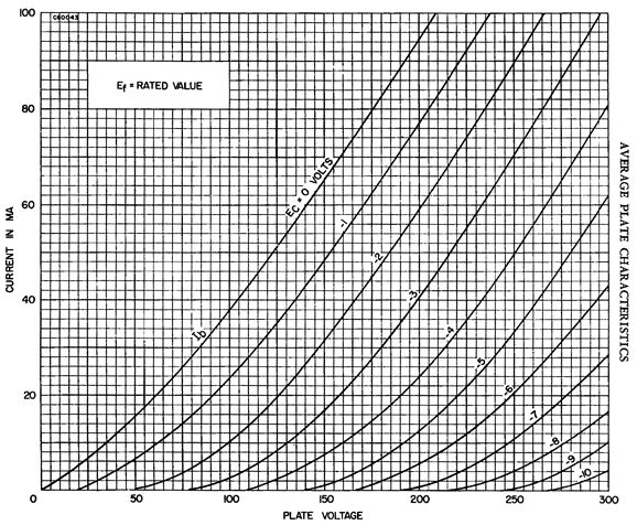
As a conceptual aid, imagine that the triode and transistor came sealed together in the glass envelope—in other words, only three external connections to the external world. The next step is to compare the naked triode's plate curves to the super-triode's plate curves. Here are the 6DJ8's plate curves from the Sylvania tube manual.
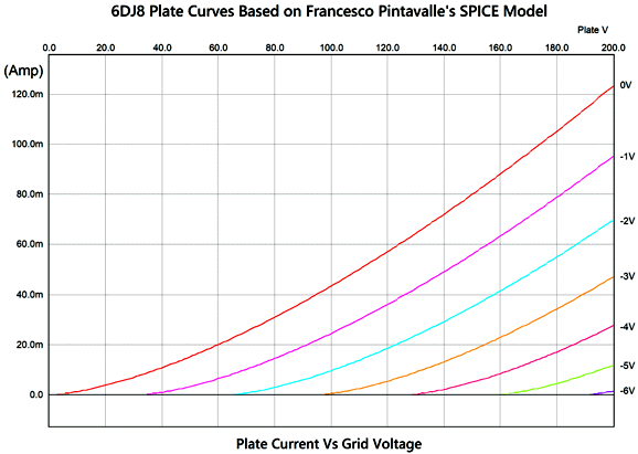
Note that 100mA of current flow with a grid voltage of 0V only occurs beyond a cathode-to-plate voltage of 200V. Here is the best SPICE model of the 6DJ8 that I have encountered.
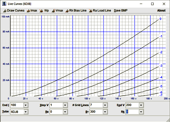
Note that 100mA of current flow does occur before a cathode-to-plate voltage of 180V. Nonetheless, this SPICE model is fairly accurate at lower plate voltages and cathode currents. By the way, here is my Live-Curves math model of the 6DJ8:
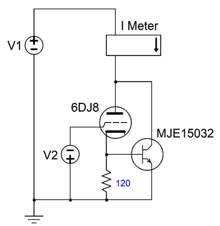
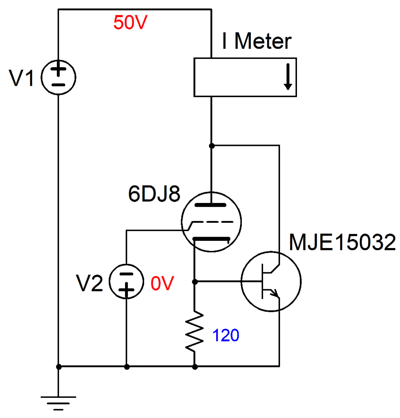
I used an actual curve-tracer's set of plotlines as the basis for my 6DJ8 math model, yet the match with the tube manual's curves is quite tight. Note the current conduction at 60 plate volts and 0V grid volts and that the current conduction is still below 100mA at 180V. Sadly, my math model is too complex to use within SPICE without first creating a new device class, namely the triode, which would include the unidirectional current conduction and the possibility of grid conduction. In other words, we would have to first hack the SPICE source code, a major undertaking; if you don't think so, just look at the SPICE's source code for the MOSFET class. If we stick to the Pintavalle SPICE model of the 6DJ8 and the SPICE model for the NPN MJE15032 transistor, however, we can derive super-triode plate curves in SPICE. We need two voltage sources and a current meter, along with a 120-ohm cathode resistor.
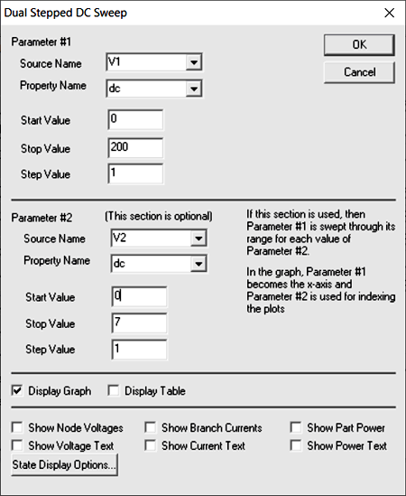
The SPICE simulation that we will run is the Dual Stepped DC Sweep.
The resulting plate curves look very much like the 6DJ8's, but DC shifted to the right and delivering insane amounts of plate current. Note that the current labeling is in amps, not milliamps. Just imagine a 6DJ8 delivering over 5A at 100V. Appearances to the contrary, the super triode is conducting current below 40V, but as the transistor hasn't seen sufficient base voltage to conduct, the current flow is in milliamps. Note that where a naked 6DJ8 cannot deliver 100mA at 200V with 0V grid voltage, the 6DJ8 super-triode delivers 33A, an increase greater than 300 fold. After I emailed my friend these graphs of plate curves, he was convinced of the viability of the super-triode arrangement. In fact, he was jazzed by the possibility. Sadly, having just made a convert, I had to point out the major liability of the super-triode arrangement: thermal runaway. The hotter a solid-state device gets, the more current it conducts. (Believe me, there's a good reason that MOSFETs and transistors are used as electronic switches.) I performed another Stepped-DC Sweep test in SPICE. This time the plate voltage was held to 50Vdc and the grid voltage to 0Vdc, while the temperature in centigrade is swept from 0C to 100C. The SPICE circuit was as follows.
The results showed a tenfold increase in idle current from 0C to 100C, from 0.1A to 1A.
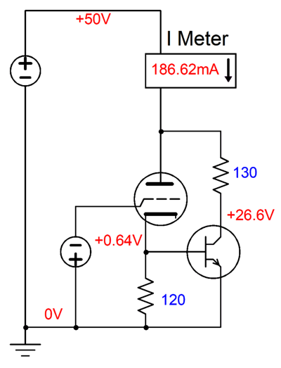
With an emitter-to-collector voltage of 50V and an idle current flow of 0.1A, we get 5W of dissipation from the transistor and with 1A we get 50W! What is needed is a negative feedback mechanism to prevent thermal runaway. One quick workaround is to add a collector resistor.
The greater the transistor's current conduction, the greater the voltage drop across the collector resistor.
Note that the NPN transistor's dissipation (5W) peaks at 30C (86 degrees in Fahrenheit), thereafter, it falls off. In other words, it's a positive relationship between temperature up to 30C, and then a negative one beyond 30C. In contrast, the resistor's dissipation linearly increases with temperature, going from 1W at 0C to 17.5W at 100C. Another workaround is to use a cathode resistor.
With the same 50Vdc plate voltage, we run another SPICE test and get the following results:
The idle starts at 98.5mA and ends at 128mA. Mind you, unlike the collector resistor, the cathode resistor will subtract from the super-triode's transconductance. Effectively, the super-triode transconductance will roughly equal the inverse of the cathode resistor's resistance; in this example, 133mA per volt. Another workaround is to load the super-triode with a constant-current source, which forces a strict limit to the idle current flow.
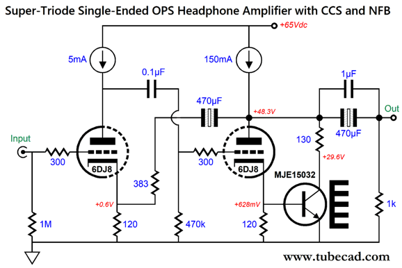
CCS The Constant-Current-Source Solution
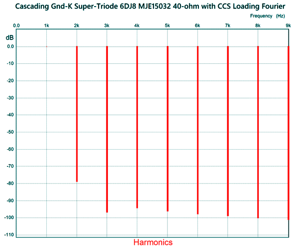
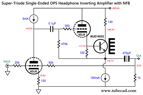
The two constant-current sources solve two potential problems: thermal runaway and power-supply noise leaking into the output signal. This super-triode-based headphone amplifier is designed to drive headphones as low as 25 ohms in impedance. The output stage is single-ended and can deliver a peak output negative current swing as almost great as the 150mA constant-current source and a positive swing equal to that of the constant-current source, which against a 40-ohm load would equal 6Vpk of peak output voltage swing and 450mW of power delivery. The 383 negative feedback resistor sets a gain of 1:4 or +12dB. The 130-ohm collector resistor both absorbs heat dissipation from the transistor and limits the maximum current flow through the transistor. Its wattage rating should be at least 5W. (If a 100ohm collector resistor were used instead, the wattage rating could be lowered to 3W.) This is a non-inverting amplifier that employs a good amount of negative feedback. With 1Vpk at 1kHz of output into a 40ohm load, the SPICE-produced Fourier graph reveals low distortion.
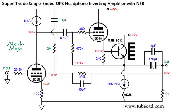
I like the greater suppression of the 3rd harmonic, but I wish the higher harmonics were further suppressed. We can also create an inverting version of this headphone amplifier, wherein the output stage functions as a cathode follower, not a grounded-cathode amplifier.
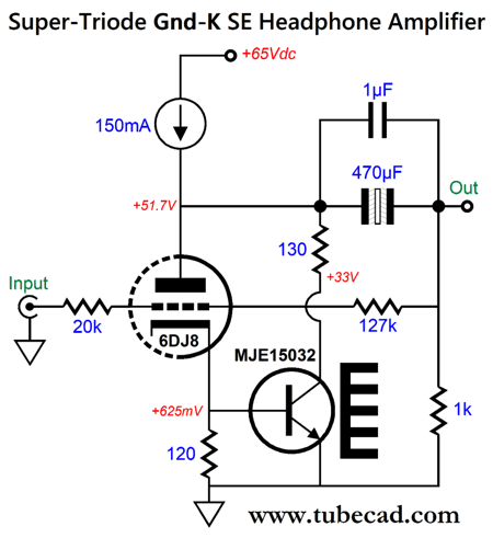
The constant-current source could be made from an LM317-HV regulator IC, along with an 8.2-ohm adjustment resistor. The input triode provides all the open-loop gain, while the output stage offers both low distortion and low output impedance. In other words, much less negative feedback is employed in this version. In SPICE simulations, I discovered that the 82k negative feedback resistor needed to be bypassed by a 10pF capacitor to prevent ultra-high-frequency peaking. I also noticed that we could forgo the 130-ohm collector resistor by using a low B+ voltage for the NPN transistor—something we couldn't do in the non-inverting design.
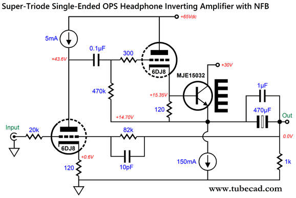
The MJE15032's dissipation is only a tad over 2W, which is close to its no-heatsink limit of 2W. Note that input triode is shielded from the power-supply noise, but the output super-triode isn't. One workaround would be to regulate the +65Vdc power-supply rail—or, we can get sneaky (i.e. clever) and introduce some Aikido mojo.
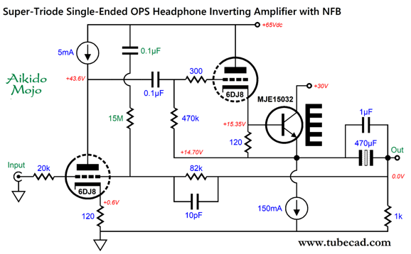
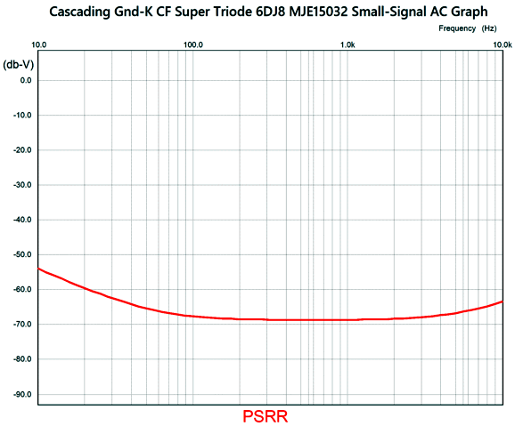
The added 0.1µF capacitor and 15M resistor inject just enough power-supply noise into the negative feedback loop to create a deep power-supply-noise null at the output. How well does the Aikido mojo work? Super well. First, we should ask what was the PSRR of the circuit without the Aikido mojo? Answer, -44dB. Here is what SPICE simulation shows.
This represents an improvement greater than -30dB. So are we done? We are never done. Elon Musk said recently that a product doesn't usually get good until at least its third revision. How can we improve this design? One idea that came to mind was that by upping the idle current we could get a free heater power supply.
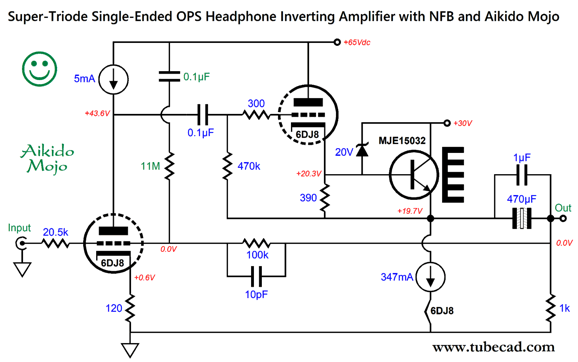
Interesting design, too bad it cannot work. Why not? The tubes must have hot heaters before they can conduct cathode current, but until the cathode draws current the transistor cannot conduct. In other words, the transistor cannot heat the he until the heaters are hot. This is a bummer of a Catch-22 situation. The workaround is to add a 20V zener diode.
At start-up, the zener conducts, thereby turning on the transistor, which in turn provides a current path for the constant-current source and heater element. Once the output triode heats up, it conducts and pulls the transistor base voltage above the zener's voltage breaking voltage, so the zener ceases to conduct. If we want to extra fancy, we could add a Broskie DC servo.
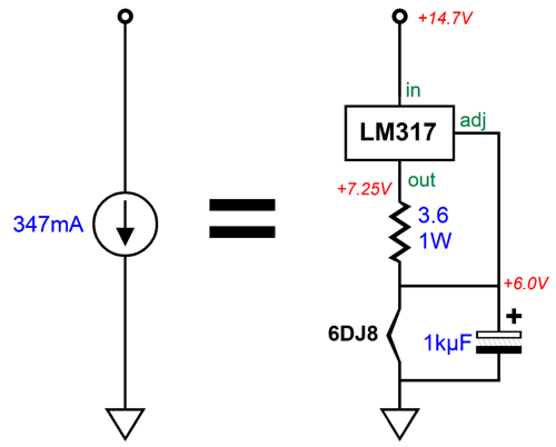
Remember that a headphone amplifier only has to deliver a few volts of output voltage swing. Thus, we can fit the 6DJ8's heater voltage drop into the 30Vdc voltage window of operation. (The tube manual tells us that the 6DJ8's heater draws 365mA, not 347mA, so what's up here? Tubes last much longer with a slightly reduced heater voltage.) Here is one potential constant-current source design.
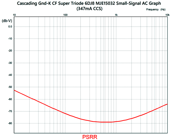
The LM317's current flow equals 1.25V divided by the adjustment resistor's value; in this example, 3.6 ohms, which equals 347mA. This amount of current against the 6DJ8's heater element resistance equals a voltage drop of about 6V. The 1kµF electrolytic capacitor shunting the heater helps slow the inrush of current into the heater, as the capacitance must be charged up first. (Now that I look at the new output stage, I see that the emitter voltage should be increased from 14.7V to closer to 20V.) Here is the PSRR graph for this fourth revision.
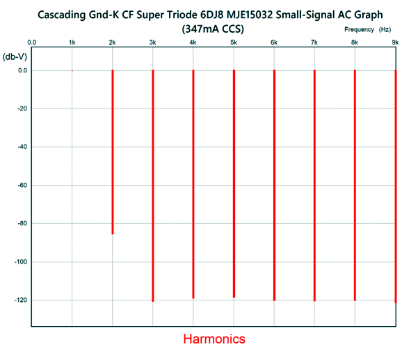
This reveals a slight improvement over the previous version. The Fourier graph proved interesting.
It looks like the graph for the non-inverting version, but better. This was, to be honest, what I expected to see. How so? I had evaluated before a simpler inverting headphone amplifier, which looked promising with 1Vpk of output into a 40-ohm load, but less promising with 4Vpk of output. Here is that simpler version.
Here is the accompanying Fourier graph:
Note the strong 2nd harmonic. In fact, I can imagine many quite liking the sound from this simpler design, due to its riper 2nd harmonic sonic signature.
Important Caveat
RC Solution
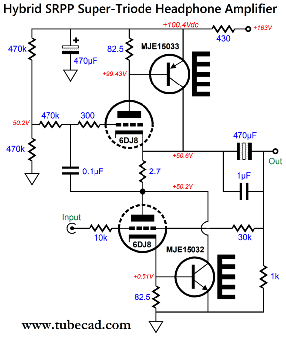
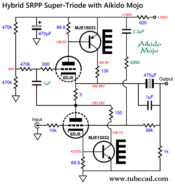
One problem that few seem to know about with the SRPP circuit is its poor PSRR, about -6dB. Of course, the RC low-pass filter formed by the 430-ohm resistor and 470µF capacitor will help, but we can do much better by introducing some Aikido mojo.
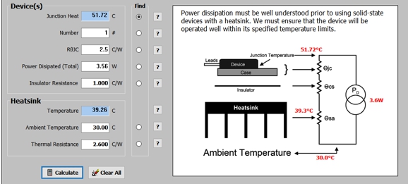
The B+ voltage of 163V is the result of rectifying up a 120Vac secondary voltage. The SRPP amplifier's gain is 1:4 or +12dB. (The assumption here is that the headphone amplifier might be driven by smart phone or tablet or laptop or external DAC.) Since the SRPP is a push-pull circuit that can deliver up to twice the idle current in peak swings, I decided to back off the idle current in this revision, which in turn reduced the transistor junction temperature.) The Idle current flow is 101.5mA, with the triodes drawing 6.5mA, leaving the transistors to make up the difference. The 620-ohm RC resistor should be rated for at least 10W. The added Aikido-mojo parts, the 2.2µF capacitor and the 499k resistor inject enough of the B+ voltage ripple into the bottom 6DJ8's grid to create a deep power-supply noise null at the output. Without the added Aikido-mojo parts, the PSRR in SPICE simulations was -68dB at 100Hz; with the Aikido-mojo parts, -96dB. A 28dB improvement translates into a 25-fold decrease of power-supply noise. In other words, it was worth the tiny expense and effort, as the alternative was to increase the RC capacitor capacitance from 470µF to 11,750µF, which would cost at least 25 times more and be simply huge. The transistor junction temperature is 52C, which was established through an iterative process that begins with good guesses and moves on by making small adjustments. I assumed a heatsink with a thermal resistance of 2.6C/W (aka 2.6K/W), such as the Avid or Boyd 530002B02500G (also the Boyd 6400B-P2G). I also assumed an ambient temperature of 30C and an isolator washer with a thermal resistance of 1C/W. I then plugged in all the values into a heatsink calculator program I created.
In SPICE simulation, the following graph resulted.
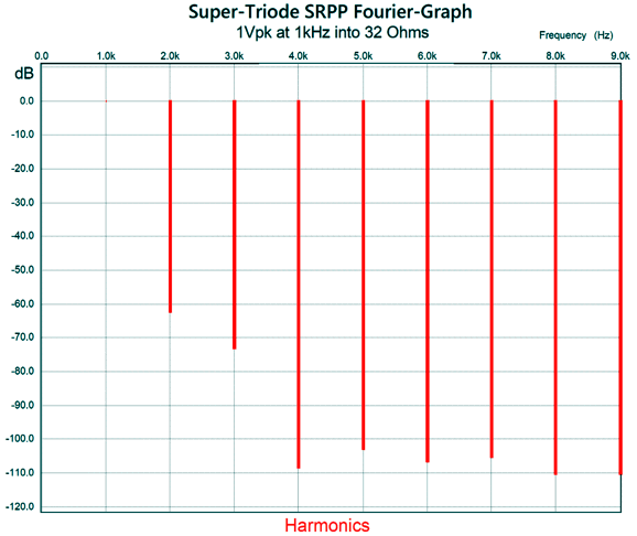
Note the negative slope beyond 40C. This is just what we want to see, i.e. an intrinsic negative feedback mechanism that prevents thermal runaway. The Fourier graph proved interesting.
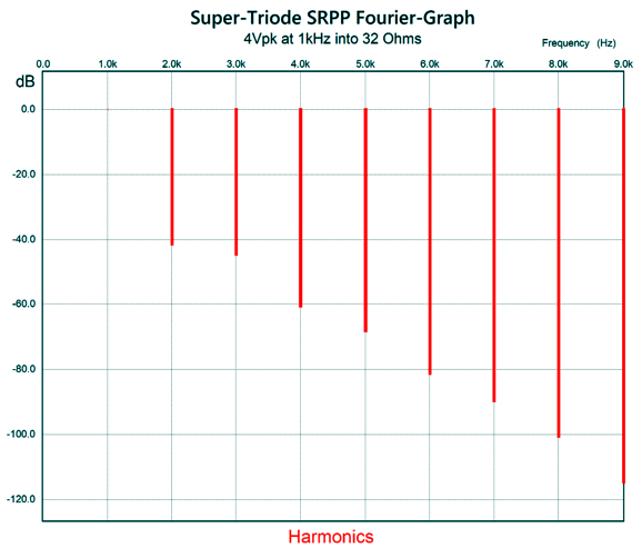
This translates into a THD of about 0.1%. With an output voltage swing of 4Vpk at 1kHz into a 32-ohm load, the distortion rises to about 1%. The output impedance was an impressive 2 Ohms.
Note the lovely single-ended cascade of harmonics. By the way, 4Vpk is a huge peak voltage swing for all but the least efficient headphones. For example, many smartphones deliver 1Vpk. What we need to remember is that four times more voltage swing equals sixteen times more power delivery.
I argued against the idea on the grounds that finding twelve German NOS tubes would be neither easy nor cheap. In addition, I pointed that all those tubes still couldn't deliver the peak output voltage swing he desired into his Grado headphones; thus, my suggestion that he look into my super-triode arrangements. I sent him the following design, but with a higher idle current.
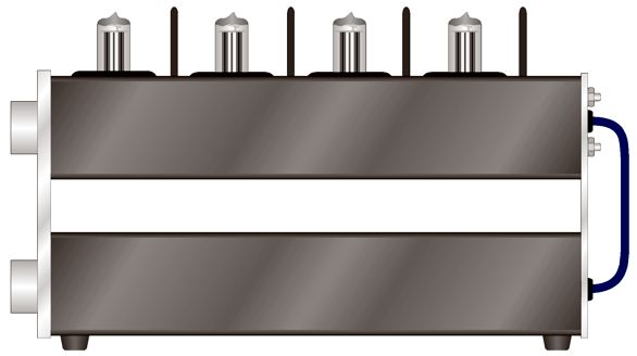
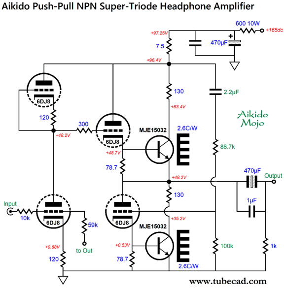
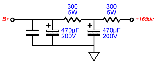
Four 6DJ8 tubes are needed for stereo, making a V4, not a V8. This is a bit silly, as no one has heard of a V4, but we have heard of an inline four. Imagine the same long extruded-aluminum enclosure of the V8 design, but with four tubes running along the length, with four 2.5-inch tall heatsinks equally spaced between the tubes, or the heatsinks flanking the output tubes or the heatsinks mounted upside down and protruding from the bottom of the top enclosure. The 600-ohm RC resistor is actually made up of two 300-ohm/5W resistors, which would allow us to add an additional RC capacitor.
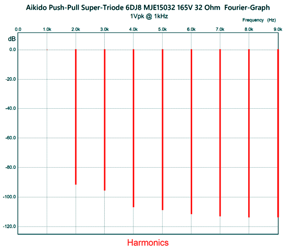
This Aikido push-pull headphone amplifier employs a negative feedback loop and delivers a gain of 1:4 or +12dB. The output stage draws 107mA, with the MJE15032 transistors drawing 100.5mA, thereby forcing 3.5W of dissipation from each transistor. In SPICE simulations, the balance between top and bottom output triodes and transistors was excellent. Like the SRPP and White cathode follower, the Aikido push-pull must be optimized to drive a target load impedance; in this example, that impedance is 32 Ohms. Simulations showed truly low distortion.
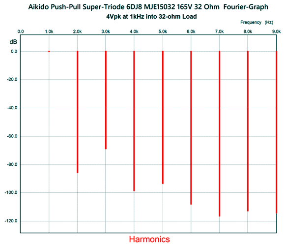
To be -80dB down translates into 0.01% distortion. At 4Vpk of output, the harmonic structure reveals the push-pull signature.
Actually, it isn't too bad. It's a pity that the 2nd and 4th harmonics are so excessively reduced. The PSRR at 100Hz was over -100dB (with the single RC capacitor). The anti-thermal-runaway negative feedback is shown in the following graph.
No doubt, many have little patience with headphone-amplifier designs, as they do not like headphones. Others want a super-triode power amplifier to drive loudspeakers, not headphones, and see 32-ohm headphones as being only four times greater in impedance than 8-ohm loudspeakers. Could this last design be modified to drive 8-ohm loudspeakers? It could, but we would have to increase the number of output triodes and transistors by fourfold. What we would get is a mighty 1W amplifier, as 4Vpeak into an 8-ohm load equals 1W. Mind you, some are building 300B-based OTL power amplifiers that only deliver 1W of output and use four 300B output tubes. One limitation to this Aikido-push-pull design is that it is a class-A design. If we are willing to break free of the confines of class-A operation, much greater output power could be realized. On the other hand, we could no longer employ my workarounds to thermal runaway of the output transistors. What to do? Let's return to the single-ended design shown before:
We can use this topology, with some modifications, such as increasing the tube B+ voltage and the constant-current source's idle current to 2A; moreover, we replace the NPN transistor with a power MOSFET. Both the constant-current source and the MOSFET will dissipate 30W each, making a total of 60W per channel, which argues for mono power amplifiers. With such an arrangement, we could reasonably get 10W of single-ended glory. Of course, a big power transformer and big heatsinks would be needed. Note how this single-ended amplifier falls short of the theoretical maximum efficiency of 25%. Why? Well, first of all it could deliver more than 10W into an 8-ohm load, so it would approach the 25%. My view was that few 8-ohm loudspeakers are consistently 8 Ohms across the audio spectrum. In other words, my 10W rating was more of a real-world rating than a lab rating. For example, sinewaves of 2Apk and 16Vpk with an 8-ohm resistor produces 16W of power. But if a loudspeaker's impedance peaks at 40 Ohms, we will never get 2A of peak current at that impedance with effectively ±15Vdc power-supply rails. And if the impedance dips down to 4 Ohms, the constant-current source limit of 2A only produces 8W of power into the 4-Ohm load.
Fact Check: A Watched Pot Will Boil Here is the story: one of the burners went out on our electric stove. We summon a repairman. He mistakenly concludes that the switch needs replacing, he returns days later with a new switch. It makes no difference, so he concludes that the burner element is at fault. (Mind you, we still had to pay for the unnecessary switch and its replacement.) He returns again with a new burner, which looks nothing like the old unit but seems to work as the burner glows. Sadly, it won't bring water to a boil or allowing the searing of meat. Since the work was guaranteed, we summon him again. This time he witnesses the pale heat and concludes that the new switch is at fault. Apparently, he likes replacing switches. He returns again with a new switch, it makes no difference—but he claims that it does. Before continuing this riveting story, let's get philosophical. I have long contended that stupidity is not the mere absence of intelligence, certainly not in the way that cold is the absence of heat. My dog lacks the intelligence to program a VCR, but he is in no way stupid. No, stupidity is not a negatively measured quality, but a positive phenomenon—positive in the sense the dictionary defines it as consisting in or characterized by the presence or possession of features or qualities rather than their absence. Stupidity can actively and aggressively be produced. A good analogy might be anti-matter or negative voltages, making stupidity something like anti-intelligence that seeks out intelligence and destroys it. Just as some are brilliantly intelligent, some are brilliantly stupid. Back to the story, we turn on the burner, and we wait. Seven minutes later, he claims it is about to boil, so I plunged my hand in the warm water. I explain that seven minutes to get less than hot-tub-warm water is pitiful. He claims that only four minutes have passed. I point out that I can do simple math; we turned on the switch at 9:37 and it is now 9:44. He claims that he started his watch at turn-on and it shows four minutes. It was then that I had an inkling that I was dealing with not just an incompetent fellow, but a possibly disingenuous fool. Fifteen minutes later, I once again plunge my hand into the water. Forty minutes later, we still don't have a boil. I dip an electronic meat thermometer into the water and it reads 180.3 degrees. He claims that it is inaccurate, so he uses his laser thermometer; but does not show me the readout, claiming that it, too, is off due to the pot being excessively reflective. I was trapped in Monty Python's "Dead Parrot" sketch
Nearing the one-hour mark, we behold a listless boil, nowhere near a pasta-adding boil. I measured 203 degrees Fahrenheit. (At 5,000 feet in altitude, water boils at 203 degrees.) He calls his supervisor, but lies to him as he describes the situation, claiming only minutes of delay, not the near one-hour torment. (I have often thought to be supremely stupid required some admixture of malice if not unalloyed evil.) Once he hangs up, I ask him if it only took a few minutes, why was he still here? He then calls the oven manufacturer, and proceeds to lie more egregiously, claiming even less time. Well, his supervisor and manufacturer agree with him: there's nothing wrong with the burner; another job well done—five visits and the 90 day warranty almost exhausted. By the way, the adjacent working burner gets well over 700 degrees hot, while his replacement burner barely cleared 500 degrees. If I were a duplicitous sort, like him, I would have claimed a 30% decrease in temperature, but I know that Celsius and Fahrenheit are relative scales, that we must start at true absolute zero before we determine ratios. Nonetheless, a 200 degree difference is a big difference. He left with the promise that his supervisor would come to analyze the situation. Soon after, his employers called to say that since the stove was working perfectly, the supervisor's visit would cost us. By the way, during our long conversation over the pot, I offered my theory, which was that heating element expanded when hot, excessively so, thereby creating a near open-circuit due to a crack, which then healed as the element cooled and contracted. He explained that I know nothing of things electrical. That might well be, but I do know that in the hierarchy of difficulty, appliance repair stands above roller-skate repair, but below bicycle repair. If only we had another new switch... My new policy is that at the first utterance of a lie, I will turn on the voice recorder app on my phone and record our conversation going forward. The challenge set for tomorrow before his supervisor is that the pot of water must come to a boil in 12 minutes, which is their standard not mine. But in my last telephone conversation with the company, they tried to move the goal post to 20 minutes; bastards. Well, I was still able to stick my hand in the water at the 20-minute mark in a test I performed this morning. Stovetop Update
Music Recommendation: This is not a big-band ensemble—instead, it is a duet of two jazz musicians, Verploegen playing the flugelhorn, while van Hulten playing the drums. This minimalist group makes the typical jazz quartet seem huge by comparison, yet the music never sounds thin, as the interplay and dialogue between the two musicians is arresting and compelling. Van Hulten does not just lay down a steady beat, but plays the drums as if it were a guitar or saxophone, reminding me, oddly enough, of great Indian tabla players, such as Ustad Allah Rakha. The recording is excellent and drums have seldom been recorded as well. Just listen to the "Smada" track to hear what I am saying. Both Amazon Music and Qobuz offer it in 24-bit and 192kHz
//JRB
Did you enjoy my post? Do you want to see me make it to post 1,000? If so, think about supporting me at Patreon.
User Guides for GlassWare Software
For those of you who still have old computers running Windows XP (32-bit) or any other Windows 32-bit OS, I have setup the download availability of my old old standards: Tube CAD, SE Amp CAD, and Audio Gadgets. The downloads are at the GlassWare-Yahoo store and the price is only $9.95 for each program. http://glass-ware.stores.yahoo.net/adsoffromgla.html So many have asked that I had to do it. WARNING: THESE THREE PROGRAMS WILL NOT RUN UNDER VISTA 64-Bit or WINDOWS 7, 8, and 10 if the OS is not 32-bit or if it is a 64-bit OS. I do plan on remaking all of these programs into 64-bit versions, but it will be a huge ordeal, as programming requires vast chunks of noise-free time, something very rare with children running about. Ideally, I would love to come out with versions that run on iPads and Android-OS tablets.
|
I know that some readers wish to avoid Patreon, so here is a PayPal button instead. Thanks.
John Broskie
John Gives
Special Thanks to the Special 92 To all my patrons, all 92 of them, thank you all again. I want to especially thank
I am truly stunned and appreciative of their support. In addition I want to thank the following patrons:
All of your support makes a big difference. I would love to arrive at the point where creating my posts was my top priority of the day, not something that I have to steal time from other obligations to do. The more support I get, the higher up these posts move up in deserving attention.
If you have been reading my posts, you know that my lifetime goal is reaching post number one thousand. I have 393 more to go. My second goal was to gather 1,000 patrons. Well, that no longer seems possible to me, so I will shoot for a mighty 100 instead. Thus, I have just 8 patrons to go. Help me get there. Thanks.
|
|||


| www.tubecad.com Copyright © 1999-2024 GlassWare All Rights Reserved |