| John Broskie's Guide to Tube Circuit Analysis & Design |
October 31 2024 Post Number 610
Happy Halloween
More Balanced Audio Maximum Output Line levels
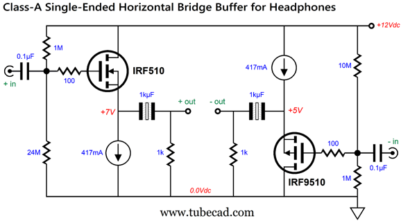
Note the inclusion of "RMS," which means that each level peaks at 1.414 times higher with sinewaves; for example, 6Vrms equals 8.45Vpk. I assume that the output voltage is measured differentially; in other words, it is measured from output to output. On the other hand, if it is measured from either the inverted output or the non-inverting output to ground, then the differential peak-to-peak output voltage swing is almost 17V. This is huge, as 17Vpk across an 8-ohm load equals 18W. Nonetheless, 8.45Vpk is still a lot of voltage swing from a DAC. It equals a bit more than 4W into an 8-ohm loudspeaker, which is more than most 2A3 based single-ended power amplifiers put out. In addition, some planer headphones require around 8Vpk to dance. Let's start with a single-ended power buffer designed to drive headphones that requires a balanced set of input signals.
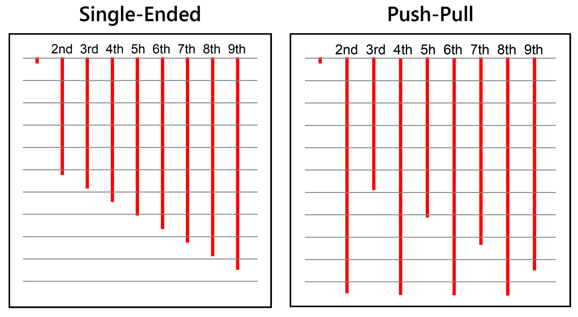
Let me indulge myself in my making the observation that only I would design such a circuit, as 99.999% of other electronic wizards would use two N-channel MOSFETs, not a pairing of N-channel with P-channel. Why did I do so? Single-ended operation, with its attendant lovely cascade of harmonics, just like those from a 2A3 or 300B based single-ended power amplifier. If I had used two N-channel MOSFETs (or two P-channel MOSFETs), the harmonic structure would resemble that of a push-pull power amplifier, not that of a single-ended amplifier.
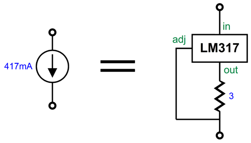
Note that sweet even-order harmonics are notched out in the push-pull output, whereas the single-ended output offers a smooth downward cascade of harmonics. Guess which makes our ears happier. No doubt, many are confused, as far as they can tell, this power buffer is a push-pull affair, with two anti-phase voltage outputs pushing and pulling away. Push-pull operation requires at least two output devices and, equally important, two phases of signal current conduction. In contrast, single-ended operation only contains one signal-current phase of conduction, although single-ended output stages can hold two or three or four or more output devices as long as all the output devices work in current phase—with all the output devices in either parallel or in opposition to each other, but all of them in current phase. Returning to the circuit, the MOSFETs are relatively low power devices, being only 43W types, but at the same time they offer relatively low input capacitance, only 180pf and 200pF of input capacitance; the 125W and same package of TO-220 pairing of the IRF640 and IRF9640 present 1300pF and 1200pF of input capacitance. The output coupling capacitors might seem overly large in value, 1kµF, but the two are effectively in series with each other, so their capacitance halves. The formula for the low-frequency cutoff frequency is simple enough: Frequency = 159155/R/C where C is in µF. Assuming a 25-ohm headphone driver, the -3dB cutoff frequency will be about 13Hz with these coupling capacitors. Note that the capacitors are low-voltage non-polarized electrolytic types, which offer far lower distortion than polarized electrolytic capacitors. Of course, they can be (and should be) bypassed with high-quality film or PIO capacitors. The 417mA constant-current source can easily be made from an LM317.
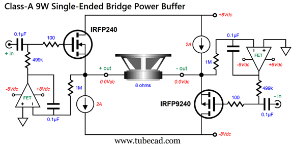
The 3-ohm resistor sees a constant-voltage drop of 1.25V, which results in 417mA of current flow, a V/R = I. The 417mA idle current might seem a bit high for driving headphones, but it does result in increased linear output from the MOSFETs. By the way, note the 12Vdc B+ voltage, which could be derived from a 12Vdc switch-mode wallwart or a linear power supply or even a 12V lead-acid battery. Since each MOSFET sees a 5V voltage drop, we can safely assume a peak differential output voltage swing of 10V, as long as the load impedance is no lower than 25 ohms, as the 417mA constant-current sources impose a strict current limit. In other words, with an 8-ohm load, the maximum peak voltage swing is equal to 0.417 against 8 which equals 3.3Vpk. If we wish to drive 8-ohm loudspeakers, then higher-power MOSFETs will be needed, along with much higher constant-current source current flow. In addition, we would use a bipolar power supply so as to avoid the need for output coupling capacitors. Here is an example of such a power buffer:
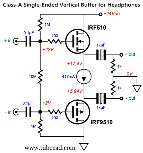
We got rid of the huge output coupling capacitors, but we must use low-value input coupling capacitors and DC servos to center the two balanced outputs ground potential. These two DC servo circuits impose a high-pass filter at 3.2Hz with a Butterworth alignment (Q = 0.707). If we want to execute a higher frequency cutoff, say 100Hz, for use in a satellite and subwoofer setup, we would alter the DC servo resistor values. See post 591 for instructions. Returning to the power buffer designed to drive headphones, note the adjective "horizontal" on the title of the headphone version of this circuit. We can arrange the circuit vertically with a 24Vdc power supply.
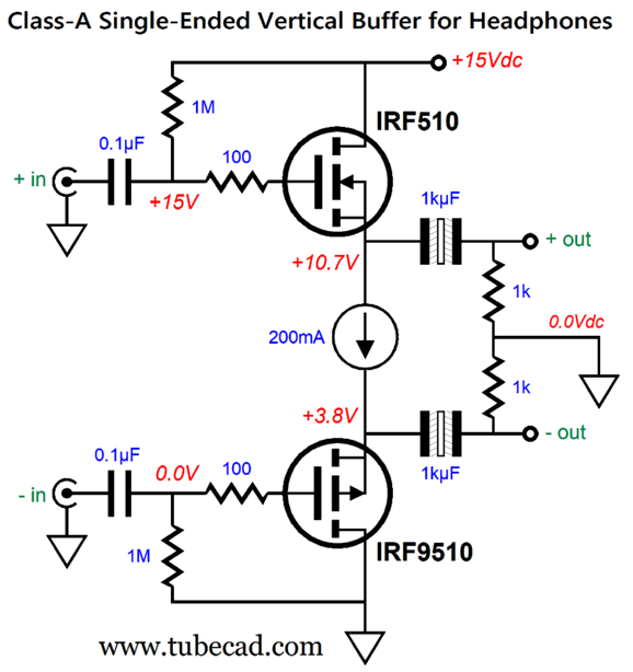
Only one constant-current source is needed, but it sees twice the voltage drop, hence twice the dissipation. (Two 210mA LM317-based constant-current sources could be placed in parallel.) If your headphones can be easily driven by your smartphone, then you could build a low-power version by dropping the B+ voltage to 15Vdc and decreasing the constant-current source to 200mA.
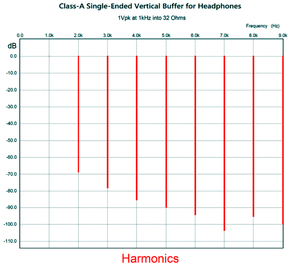
Now, a single LM317-based constant-current source can be used. (Just use a 6.2-ohm idle-current setting resistor.) This balanced-output power buffer should be able to deliver close to 6V of peak output voltage swing into 32-ohm headphones. SPICE simulations of this lower-voltage/lower-current version revealed a lovely single-ended cascade of harmonics in the following Fourier graph.
Bipolar Shunt Regulator
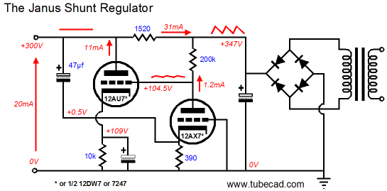
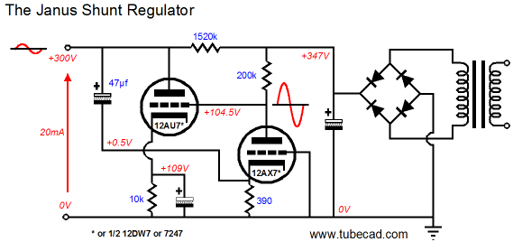
The Janus fed-forward some of the raw rectifier-induced ripple to the output shunting device (12AU7 triode) which met the ripple with a counter-conduction in current that resulted in power-supply noise null at the output. At the same time the 47µF capacitor relayed the signal-induced power-supply noise to the negative feedback device (the 12AX7 triode), which in turn amplified the noise signal, thereby allowing the shunting device to counter its presence.
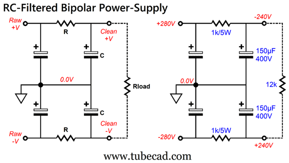
Well, with a constant-current draw balanced circuit, we can forgo this two-directional arrangement and concentrate on just canceling the rectifier ripple. Let's begin with a simple RC-filtered bipolar power supply that uses only RC resistors and capacitors to clean up the bipolar output voltages.
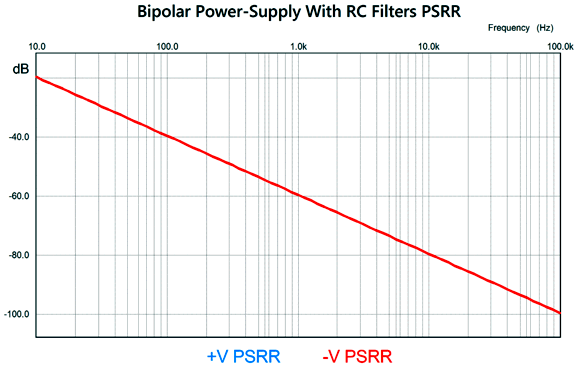
The larger in value the resistors and capacitors are, the greater the attenuation of the ripple at the outputs. In the design example on the right, we see a 40mA load circuit being powered. The SPICE-produced graph shows a healthy -40dB attenuation at 100Hz. Negative forty dB translates into divide my one hundred. Thus, if 100mV of ripple was present at the rectifiers, the ripple reduces to 1mV at the RC filter's output.
The SPICE simulation assumes perfect capacitors, i.e. capacitors without effective-series resistance (ESR) or effective-series inductance (ESL), the first of which will produce a horizontal flat line at some high-frequency, while the latter will create a V-shaped plotline that begins climbing at some high-frequency. (Of course, bypassing with a high-frequency capacitor helps.) We can augment the passive RC filtering with active devices (MOSFETs or transistors) to increase the PSRR.
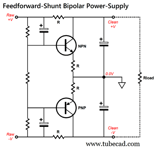
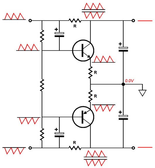
The raw rectifier ripple is fed into the transistor bases which their emitters follow, thereby creating an anti-phase current conduction. Since the resistors labeled "R" all share the same resistance value, the output voltages see a cancellation of the ripple.
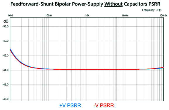
If we remove the two output capacitors, SPICE simulation will reveal the effectiveness of just the series resistors and transistors.
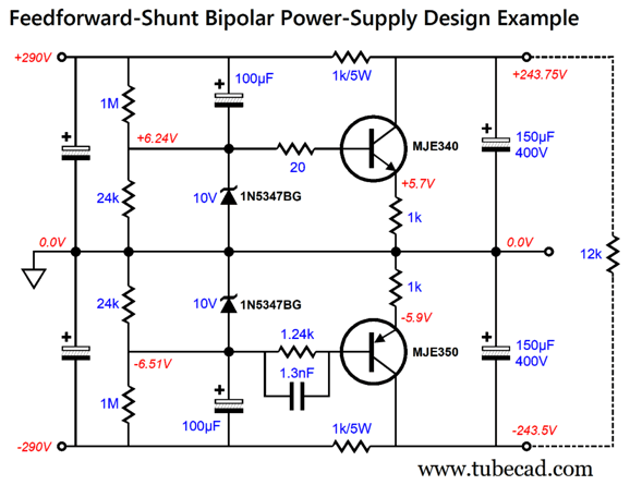
By the way, it took some sneakiness to get the two plotlines to overlap so nicely. Here is the actual circuit I modeled in SPICE.
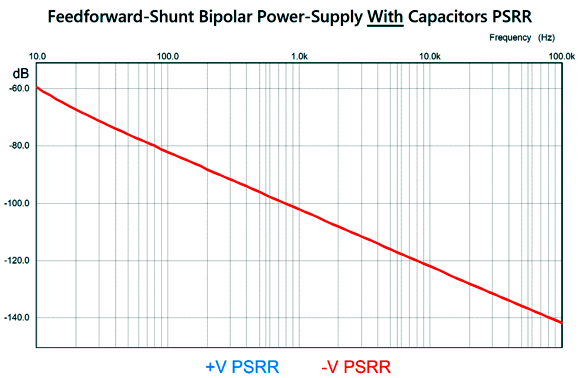
Yes, it looks more complicated than you might have imagined it needed to be. The 10-volt zeners are there to protect the transistors at turn-on and turn-off. The 20-ohm resistor functions as a base-stopper resistor that prevents high-frequency oscillations, while the 1.24k resistor also acts as a base-stopper, but in addition it balances the PNP transistor's PSRR to that of the NPN transistor. The transistors dissipate almost 1.5W of heat, so a small clip-on heatsink should be used. The output 150µF capacitors can be bypassed by high-quality film capacitors. Here is the SPICE-produced PSRR graph for the circuit with the output capacitors.
As we would expect, we see a -44dB greater attenuation of the power-supply noise at the outputs, which is an additional hundredfold improvement, i.e. 10,000 times reduction in ripple.
Aikido-Mojo Balanced Amplifier
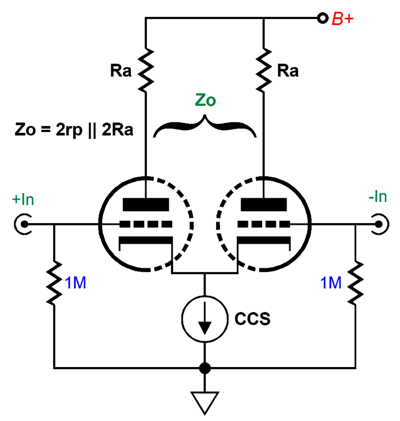
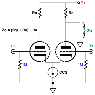
Because triodes present plate resistance (rp), the differential output impedance can prove surprisingly low. For example, a 6AS7 has an rp of 280 ohms. When the load doesn't bridge the two outputs, but terminates into ground, the output impedance is the following:
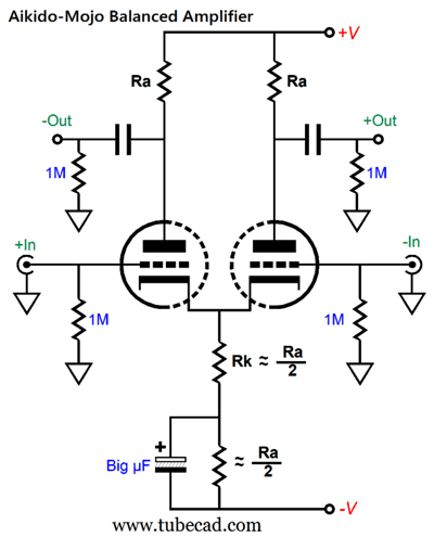
One major problem with the tube-based differential amplifier is that its' PSRR is weak (with the constant-current source cathode loading, it is almost nonexistent). One workaround is to inject some Aikido mojo.
The assumption behind this circuit is that the bipolar power supply presents equal but out-of-phase ripple on its two power-supply rails. If the reservoir capacitors are not matched in capacitance or if the center-tapped power transformer is not center-tapped correctly, the resulting imbalance will undermine the circuit's potential PSRR. A simple test requires two matched power resistors:
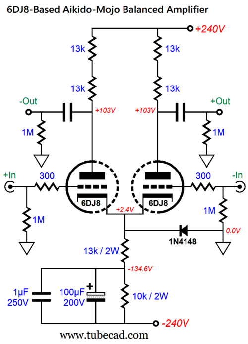
Ideally, we should see zero AC voltage. Here is a 6DJ8-based design example:
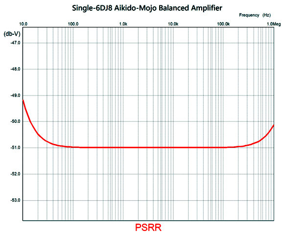
Once again, the design circuit looks overly complicated. The 1N4148 signal diode only becomes forward biased at turn-on, while the cathodes are still cold and not conducting. The two 13k plate resistors in series increase both the resistor wattage and lowers voltage-induced distortion from the plate resistors. The 10k cathode resistor shunted by the large-valued capacitor is what produces the Aikido mojo, as the 13k becomes the effective cathode resistor value. Speaking about Aikido mojo, here is the SPICE-produced PSRR graph.
Note the extension beyond 100kHz. The only potential downside to this design example is its high gain (+28dB differentially). Of course, in certain applications, such a high gain becomes a huge feature; for example, when driving a unity-gain bridge power buffer that drives loudspeakers, such as the one shown in the previous section. Well, another potential downside is the still relatively high output impedance. We can lower the gain by using a 6SN7 or a 12AU7 in place of the 6DJ8 and by adding two cathode followers.
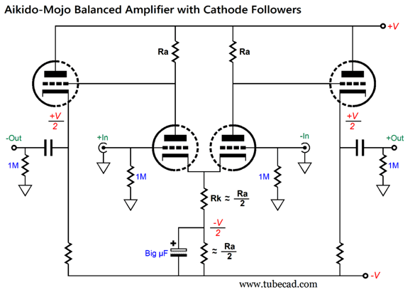
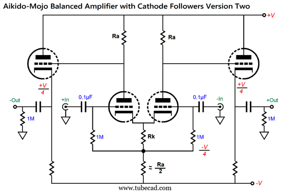
By setting resistor Rk to roughly half the plate resistor value, we obtain an excellent PSRR. An alternative version eliminates the big-µF capacitor by adding two input coupling capacitors.
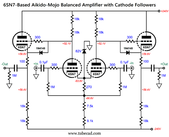
Note that the differential amplifier's cathodes and the cathode follower's cathodes span a voltage differential equal to half the B+ voltage. Also note that the average of these two voltages is zero volts. In other words, we can ground the heater power supply, thereby splitting the voltage differential. With the first version, the heater power supply must be DC referenced to 1/4th the B+ voltage. Okay, time for a design example.
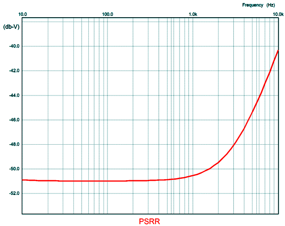
The zener and signal diodes are there to protect the cathodes at start-up. By the way, the zener could be a 1N5375BG. If the gain still too high, we can replace the single 270-ohm cathode resistor with two 536-ohm cathode resistors, one for each triode. Here is the SPICE-generated graph of its PSRR.
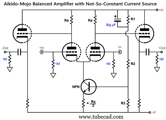
Now, imagine superimposing this amount of attenuation upon the feed-forward shunt bipolar power supply. Where this circuit falls down is on the implicit promise of a high common-mode rejection ratio (CMRR), as it only delivers a CMRR of -14dB. Mind you, if the power amplifier being driven does offer a high CMRR, then this failing might not be a concern. Nonetheless, a high CMRR is a desirable feature in a balanced line-stage amplifier. What to do? Get clever, that's the answer. Here's the problem: if we replace the input differential amplifier's cathode resistor with a constant-current source, we get great CMRR, but miserable PSRR. What if we use a not-so-constant-current source? Imagine that the positive rail voltage spikes up from 200Vdc to 201Vdc. With a truly constant-current source loading of the input differential amplifier's cathodes, the two anti-phase outputs will also jump positive by 1V, as the plate resistors see a constant-voltage drop at idle; thus, if the B+ voltage jumps up a volt, so too must the plate voltages. (The current conduction remains constant, as the constant-current source creates a small positive jump in the joined cathode voltage. How much? 1/(mu +1) as much.) Let's say the plate resistors are 10k in value and the constant-current source draws 10mA. Each triode and each plate resistor therefore sees 5mA of current flow, with each plate 10k resistor seeing a 100V drop. Now, if the constant-current source also saw a small increased jump in current flow, say going from 10mA to 10.2mA, the plate resistors experience a voltage drop of 101V, which would leave the plate voltages unaltered. In other words, we need to provoke a ripple-induced variation in the current source's current conduction. How do we perform this feat of magic? We inject a sampling of the ripple into the constant-current source.
The three resistors in series form AC and DC voltage dividers. In terms of DC, the voltage division is equal to R1/(R3 + R2 + R1); in terms of AC, R1/(R2 + R1). In theory, resistors R2 and R3 share the same value, but the NPN transistor's base draws some current, so in practice the values will differ. Here is a design example that uses 6SN7s throughout.
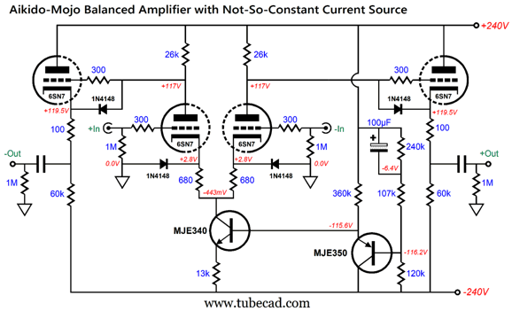
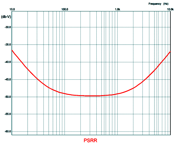
The Added PNP transistor creates a two-transistor diamond topology with the NPN, which undoes the NPN's base-to-emitter voltage drop and allows higher-valued resistors in the resistor string. The 1N4148 diodes offer triode protection at turn-on and when a tube is missing from its socket. For example, if the input tube (in the center) were missing, the cathode follower triode grids would see +240Vdc; with the diodes in place, the grids would see 191Vdc, while the cathodes would see 190Vdc. At startup, the constant-current source will ramp-up to full current conduction far more quickly than will the input triodes, but the diodes prevent the cathodes from being pull down in voltage more than -0.7V. The oddly-valued resistors, 26k and 60k, are so labeled as they are in fact multiple resistors in series. The 26k is made up of two 13k resistors; the 60k, three 20k resistors; the 360k, three 120k resistors; and the 240k, two 120k resistors. In SPICE simulations, the distortion was fantastically low and the CMRR and PSRR were quite acceptable.
Music Recommendation: Annie Lennox's Nostalgia The same way I discover many albums: I pick a song that I know well, in this case, "I Put A Spell On You," written and recorded by "Screamin' Jay" Hawkins in 1956 and domesticated by Nina Simone in 1965; and then I do a search in Amazon Music or Qobuz or Tidal for covers of the song, which often results in hundreds of tracks. I go down the list, song by song, giving each a fair chance to catch my attention and approval, which doesn't take all that long. Occasionally, I am music-struck, which prompts me to delve into other songs by the singing artist. This method works due to my knowing the song well, thereby avoiding the duds that every singer produces, even the best of the best. Indeed, nevertheless very good songs first heard don't seem all that good. Prior to using my technique with streaming music services, I read reviews, borrowed CDs from friends and the library, and asked friends for recommendations. My new procedure is far more efficient. Recently, I was quite taken by Samantha Fish's cover of "I Put A Spell On You." She plays a mean blues guitar and sings in a beguiling bluesy-jazzy fashion that I quite enjoy.
The search was on. Here are the results, in alphabetical order, of captivating renditions of the song I discovered before I was exhausted:
The first standout was by a Norwegian singer, Angelina Jordan, a nine-year old girl singer! Mercy. Talk about child prodigies. Hearing her sing makes me believe in reincarnation. If Bobbie Gentry were not still with us, I could imagine her to be Angelina's spiritual forbearer. Nine years old! Most, if any, nineteen-year olds aren't anywhere near as mature. Against my abiding opposition to YouTube videos, here is the link to her singing the song, youtube.com.
(Amazon Music offers this track in 24-bit, 192kHz. ) I will skip Lennox for now and jump ahead to French-Canadian guitarist and jazz singer, Chantal Chamberland. Here was another singer I had never heard of before, but who is now on my radar in a big way.
My music radar also spots previously unknown-to-me Brazilian singer, IZA (aka Isabela Cristina Correia de Lima Lima).
Finally, we come to Annie Lennox. Her cover of the song made me jump to attention. Sadly, her cover of Billie Holiday’s original and famous singing of "Strange Fruit" failed to deliver anything new, just her lovely voice. Isn't that enough? No. She makes pretty what should be horrific. In contrast, her cover of "Georgia on My Mind" works beautifully.
//JRB
Did you enjoy my post? Do you want to see me make it to post 1,000? If so, think about supporting me at Patreon.
User Guides for GlassWare Software
For those of you who still have old computers running Windows XP (32-bit) or any other Windows 32-bit OS, I have setup the download availability of my old old standards: Tube CAD, SE Amp CAD, and Audio Gadgets. The downloads are at the GlassWare-Yahoo store and the price is only $9.95 for each program. http://glass-ware.stores.yahoo.net/adsoffromgla.html So many have asked that I had to do it. WARNING: THESE THREE PROGRAMS WILL NOT RUN UNDER VISTA 64-Bit or WINDOWS 7, 8, and 10 if the OS is not 32-bit or if it is a 64-bit OS. I do plan on remaking all of these programs into 64-bit versions, but it will be a huge ordeal, as programming requires vast chunks of noise-free time, something very rare with children running about. Ideally, I would love to come out with versions that run on iPads and Android-OS tablets.
|
I know that some readers wish to avoid Patreon, so here is a PayPal button instead. Thanks.
John Broskie
John Gives
Special Thanks to the Special 88 To all my patrons, all 88 of them, thank you all again. I want to especially thank
I am truly stunned and appreciative of their support. In addition I want to thank the following patrons:
All of your support makes a big difference. I would love to arrive at the point where creating my posts was my top priority of the day, not something that I have to steal time from other obligations to do. The more support I get, the higher up these posts move up in deserving attention. If you have been reading my posts, you know that my lifetime goal is reaching post number one thousand. I have 393 more to go. My second goal was to gather 1,000 patrons. Well, that no longer seems possible to me, so I will shoot for a mighty 100 instead. Thus, I have just 8 patrons to go. Help me get there. Thanks.
|
|||
| www.tubecad.com Copyright © 1999-2024 GlassWare All Rights Reserved |


